→ LiFePO4 Batteries
Mfg. / Part #: Renogy 200Ah LIFEPO4 Tags: battery, electrical
Summary
- 2 x 200Ah Lithium Iron Phosphate (LiFePO4) Renogy batteries
- Victron BMV712 battery shunt for monitoring State of Charge and controlling the main-battery-disconnect contactor for under voltage or state of charge trip off.
- wired into a custom copper bus bar through ML-RBS which functions as the main shutoff switch.
System Diagram:
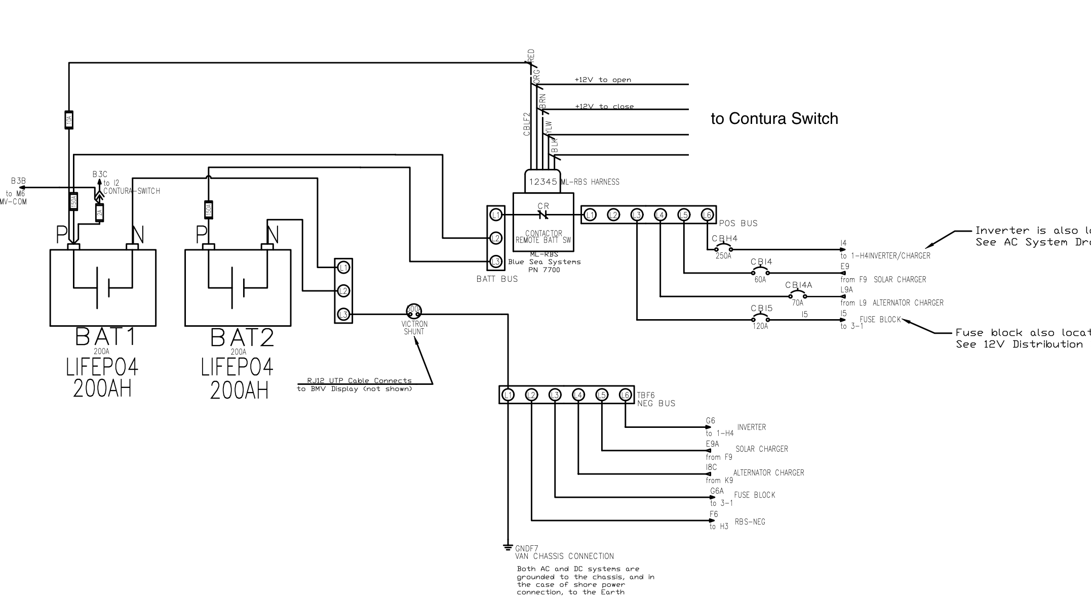
(See full resolution pdf at DWG-02-BATTERY-COMPARTMENT)
The batteries are Renogy brand 200Ah LiFePO4 with integrated bluetooth. The (2) 200Ah batteries are wired in parallel, to deliver 400Ah of storage at the nominal 12 volts.
The chemistry Lithium Iron Phosphate, or LiFePO4, is relatively new and expensive. The benefits over, e.g. AGM or Lead Acid is that you can take it down to 0% State of Charge (SoC) without totally destroying the battery’s expected number of life cycles. Note that taking it down to low SoC still does depreciate the lifetime of the battery, just not as bad as other chemistries. Renogy claims 4000 cycles on this battery, but that is dependent on usage.
Typical charging voltages are 14.2V and typical discharging voltages (active load) are 12-13V. Discharging, e.g. when the induction stove is on, will always depress the voltage, more so at low SoC.
⚠️ If you see voltages out of the typical (charging ~14.2, discharging ~12-13) you may want to take a closer look at the battery health.
A typical LiFePO4 battery SoC vs voltage curve is as follows:
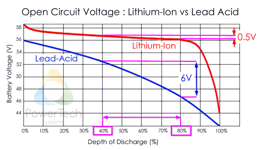
⚠️ Due to the flatness of the LiFePO voltage vs SoC curve, we cannot use voltage as a good measure of how much energy is left in the battery → this is why we need a good shunt monitor (→ battery-monitor-and-relay)
You can inspect the battery health by performing load tests (search on Youtube). Each battery should be tested separately, as one bad battery can draw the voltage down of the other.
To know the State of Charge we use the Victron BMV-712 which is connected to the Battery Shunt - all current must go through this shunt so it knows how much has left or entered the battery system at any moment
In the diagram you can see the Shunt is connected between the Negative of the paralleled batteries and the main negative bus bar (labeled 0V). All current must go through this return path, so the Shunt passes this information to the BMV, which shows the State of Charge on the display, or the app.
Usage Notes
⚠️ In general, taking the battery to a low State of Charge will reduce the lifetime of the battery, so be conscious of this when going under 50% (although the LiFePO4 batteries can go all the way to 0%, it is still not recommended).
⚠️ The batteries should not be charged when the temperature is below freezing. Make sure the Victron Connect app has the Smart Solar Charger set to not charge for temperatures below 2 degrees celsius, and that there is an alarm set for low temperature in the BMV relay.
Definitions
- SoC: State of Charge, expressed in % full
- DoD: Depth of Discharge; DoD is just the complement of SoC: DOD = 100% - SoC
- Ah: Ampere-hours, represents a unit of energy storage, similar to Watt-hours
- 1Ah is the amount of energy equal to 1A charging or discharging for one hour
- LiFePO4: Lithium Iron Phosphate - a type of battery chemistry
- BMS: Battery Management System - protects the internal battery cells from over/under voltage (usually inaccessible to the user)
- BMV: Battery Voltage Monitor - here we are talking about the Victron BMV 712; this provides the system level over and under voltage protection
Aside
You’ll notice the Batteries page featured image is different than some of the others. This is because I originally built my own bank out of individual 3.65V cells, and later upgraded to a trusted brand before selling the van (→ 12-honorable-mentions).
CAD Drawings
Full-size PDF CAD diagrams of the system can be found below:
- DWG-01-AC-SYSTEM(shows the inverter/charger and the shore power hookup)
- DWG-02-BATTERY-COMPARTMENT (shows the connections in the main electrical battery compartment and also the solar and alternator charger systems)
- DWG-03-12V-SYSTEM (shows the 12V distribution fuse block, branch circuits, and loads)