→ Battery Disconnect Switch
Mfg. / Part #: Blue Sea ML-RBS 7700 Tags: electrical
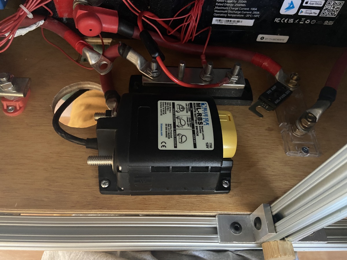
This component is the main battery switch which actually has two components - the latching relay and the “contura” control switch which is the pushbutton switch that controls the latching relay.
⚠️ The ML-RBS must be in the ON position (yellow knob facing down) and the top of the yellow knob must be depressed - this is the fully latched ON position
Picture of the ML-RBS disconnected. The control switch is through the hole on the other side.
Instruction manual wiring diagram:
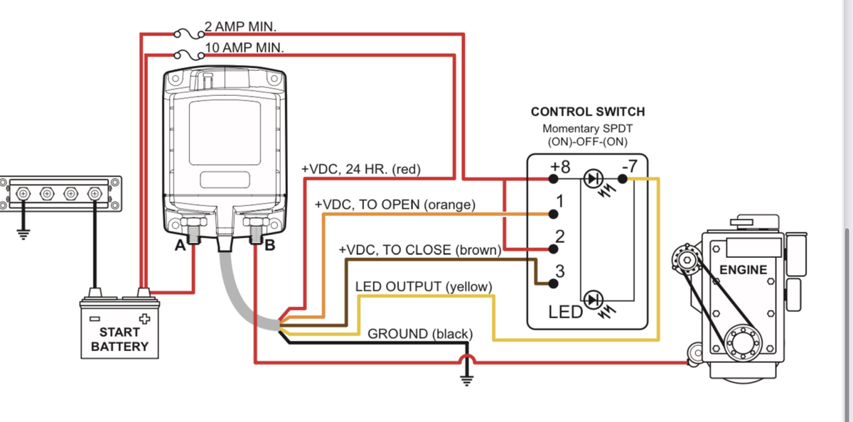
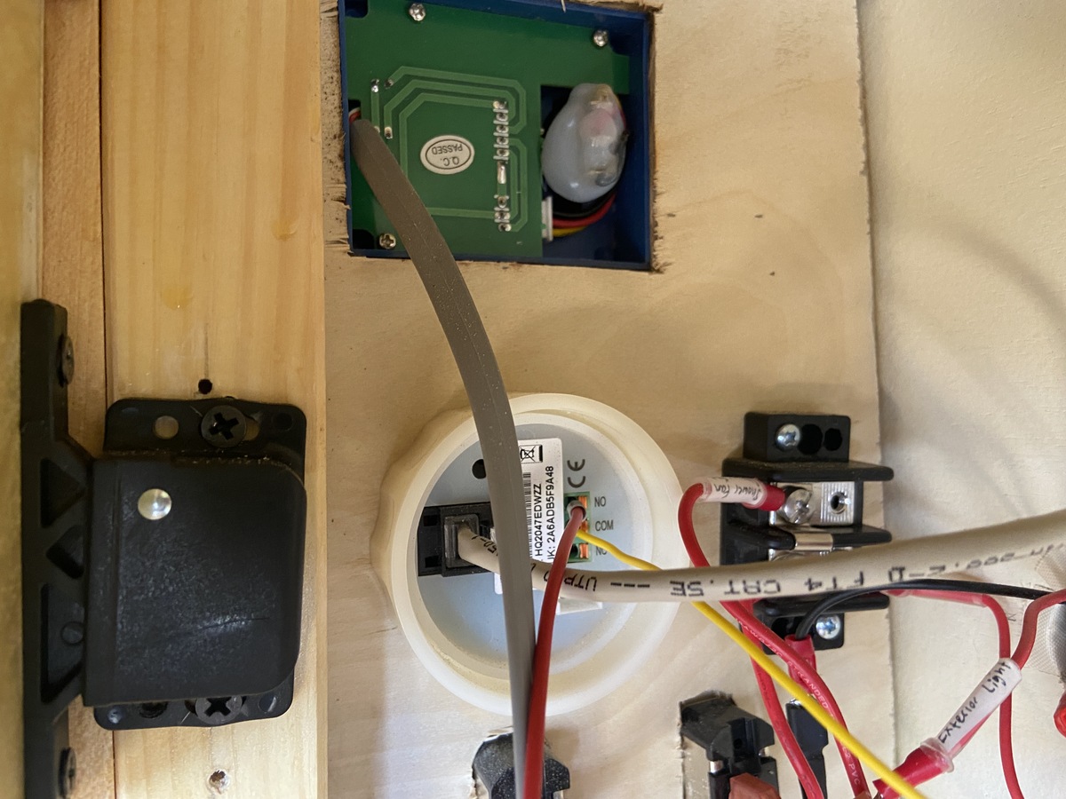
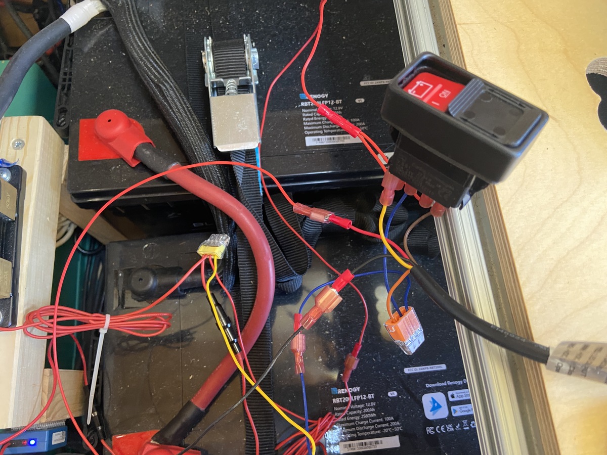
Actual wiring. The only difference is that we have added an input to Pin 1 which is now connected to the Normally Open relay of the Victron BMV 712. +12V on this pin will force the ML-RBS to Open thus disconnecting the batteries from the system. (From left to right: BMV diagram, control switch diagram, actual wiring in the back of the BMV, actual wiring for the control switch)
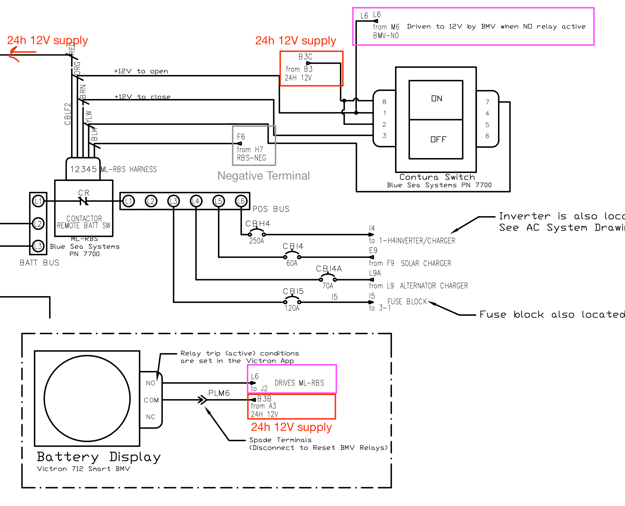
CAD Drawings
Full-size PDF CAD diagrams of the system can be found below:
- DWG-01-AC-SYSTEM(shows the inverter/charger and the shore power hookup)
- DWG-02-BATTERY-COMPARTMENT (shows the connections in the main electrical battery compartment and also the solar and alternator charger systems)
- DWG-03-12V-SYSTEM (shows the 12V distribution fuse block, branch circuits, and loads)
Next: alternator-charger